
Learn key MCAT concepts about electrostatics, magnetism, and circuits, plus practice questions and answers

(Note: This guide is part of our MCAT Physics series.)
Table of Contents
Part 1: Introduction to electrostatics, magnetism, and circuits
Part 2: Electrostatics
a) Charge
b) Conservation of charge
c) Coulomb's Law
d) Electric field
e) Electric potential
Part 3: Circuits
a) Voltage and electromotive force
b) Current
c) Resistance
d) Ohm's law
e) Capacitors
Part 4: Magnetism
a) Lorentz force
b) Magnetic field and current
Part 5: High-Yield Terms and Equations
Part 6: Passage-Based Questions and Answers
Part 7: Standalone Questions and Answers
-----
Part 1: Introduction to electrostatics, magnetism, and circuits
Electricity and magnetism (E&M) is a field of physics that describes interactions between charged particles. The topics covered here can be a little daunting because, unlike mechanics, E&M describes phenomena that are less readily observable in everyday life. Nevertheless, with the help of analogies and visualizations, even this topic can become intuitive. On the MCAT, electrostatics, magnetism, and circuits are considered to be medium-yield topics. While you may not be tested directly on these topics, they will be important in the context of neurological circuits and instrument design.
Receive Your Free MCAT Question of the Day
Get every last bit of practice in before test day with a free MCAT question delivered straight to your inbox daily.
-----
Part 2: Electrostatics
Electrostatics is the study of electromagnetic phenomena at equilibrium—that is, systems in which there are no moving charged particles. This is in contrast to the study of electromagnetism in circuits, which consists of moving charged particles.
a) Charge
The most fundamental quantity in electrostatics and magnetism is charge. Charge is a physical property of matter that causes the particle to experience a force in an electric field.
It may be helpful to compare the concept of a particle’s charge to the concept of an object’s mass: just as mass is the amount of matter that is subject to gravitational fields, charge represents a quantity within a particle that is subject to electric fields.
Charge comes from protons and electrons. Charge is a scalar, and it is measured in units of Coulombs (C).
All charge is made of combinations of protons and electrons. Protons and electrons are elementary charges, which means they are the smallest possible units of charge. The magnitude of their charge is 1.6 x 10⁻¹⁹ coulombs. In the case of protons, this value is positive; for electrons, this value is negative. (Neutrons, the third building block of atoms, have no charge.)
b) Conservation of charge
When the charge of an object changes, it does so because some number of protons or electrons move to another object. No protons or electrons are created or destroyed but instead are relocated to another place. This principle is called the conservation of charge.
Consider a conductor that has no net charge. After creating a charge on it (more on this later), either end of the conductor will gain or lose charge to create a positive or negative pole. However, since charge is conserved, the net charge of the entire conductor will remain zero.

Figure 1 Charge is conserved, even when poles gain negative or positive charges.
c) Coulomb’s Law
Recall that opposite charges attract, and like charges repel. Formally, this rule is stated by Coulomb’s law:
F = −kq1q2/r2
where F = the force exerted between the charges,
k = Coulomb's constant = 8.98 × 10⁹,
q1, q2 = the two charges,
r = the distance between the two charges
Coulomb’s law provides us a vector representing the amount of attractive force between two charged particles. As with all vectors, we must keep the direction in mind. There are a few methods to do this.
A simple method to do so is to plug in the magnitudes of each particle and decide the direction at the end of the problem. With two particles, this is as easy as remembering that the force should attract opposite charges together and repel like charges apart.
A slightly more difficult method is to keep track of the direction the whole time. Coulomb’s law states the force on just one of the charges, such as q1. Then r has to be the distance from q1 to q2. If you imagine the charges on the x-axis, r will either be positive (point rightwards) or negative (point leftwards).
Remember the negative in front of the whole equation and the different charges. If the charges are opposite, their product will be negative and will “cancel” with the negative sign in front. If they are the same sign, their product will be positive and will not cancel. If the negative sign in the front of the equation is canceled out, the force on q1 will point in the same direction as the arrow from q1 to q2. In other words, it is attractive. If the negative sign remains, the force will point in the opposite direction. In other words, it is repulsive.

Figure 2 The signs of the charges determine whether the force points in the same direction as the distance vector connecting them.

Figure 3 Coulomb's law can be applied to systems with multiple charges.
d) Electric field
An electric field is a region in which a charge will feel a force. The equation for the force experienced by a charge in an electric field is very simple:
F = E × q
where F = the force exerted on the charge,
E = the electric field,
q = the value of the charge
Notice that the electric field is a vector, and therefore has positive or negative directions. Thus, positive charges will experience a force in the same direction as the electric field, and negative charges will experience forces in the opposite direction.
Electric field is given in units of newtons per coulomb (N/C), or volts per meter (V/m).
Field lines are used to graphically represent electric fields. We represent an electric field as a collection of straight arrows. The relative strength of an electric field is given by the density of the arrows. (The same is true for all vector fields.)
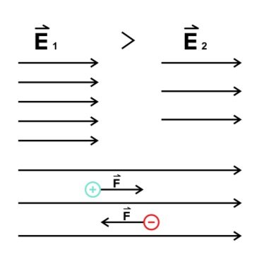
Figure 4 Field lines for uniform electric fields.
When comparing Coulomb’s law and the force on charge in an electric field, you might notice that the equations would be the same if:
E = −kq1/r2
This is because the value
−kq1/r2
represents the electric field created by charges. So, Coulomb’s law is actually just a specific case of a force due to an electric field.
Positive charges create fields that point outward, and negative charges create fields that point inward.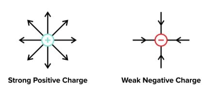
Figure 5 Electric fields have positive or negative charges
The fields generated by individual point charges will interact with each other in a predictable manner.

Figure 6 Field lines generated by two charges.
An induced charge is an artificially created distribution of charge that results from placing a conductor in an electric field. A conductor allows charge to move freely; thus, when a conductor is placed in an electric field, positive charges are free to move in the direction of the electric field and negative charges are free to move in the opposite direction. This migration of charge will continue to build until the field within the conductor—created by the new orientation charges—is large enough to completely counteract the external field.
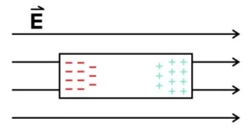
Figure 7 Induced charge on a conductor in an electric field.
d) Electric potential
Electric potential is the amount of work per charge needed to move the charge a certain distance inside of an electric field.
V = E × d × cosθ
where V = electric potential,
E = a constant electric field,
d = distance moved,
θ = the angle between the field and the distance moved
Electric potential and electric fields behave similarly to gravitational potential and gravitational fields. Imagine electric potential as a “hill.” The height of the hill represents electric potential, and the slope and gravitational field represents electric field.
In kinematics, gravity pulls everything downhill. Electric fields will pull positive charges uphill while pushing negative charges downhill.
The unit of electric potential is Joule per coulomb, or volt (V). To convert from electric potential to the electric potential energy of a charge inside that potential, simply multiply the charge that is present by the electric potential.
UE = q × V
Using the same analogy of electric potential as a topography, equipotential lines depict the contour lines of the electric potential. The electric potential is the same along equipotential lines, which means that it takes no work to move charges along them.
Equipotential lines are always perpendicular to electric field lines. The distance between them indicates how strong the electric field is.
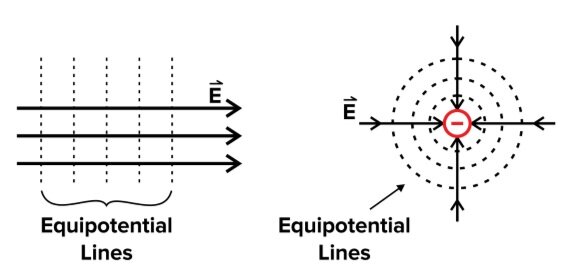
Figure 8 Equipotential lines indicate areas where force is experienced equally.
-----
Part 3: Circuits
Imagine a system with a source of positive charges and a source of negative charges. Between the positive and negative forces, there will be an electric field. If a conductor is placed in that field, the charges inside of the conductor will separate but cannot travel anywhere. However, by using an additional conductor to connect the two sources, a “highway” is created, which will allow negative and positive charges to travel.
This is the idea behind circuits. When two points with different electric potentials are connected, charges will spontaneously flow across the connection. A circuit is a closed path that allows current to flow from one place to another.
A typical circuit diagram will include a source of voltage, a wire, and a resistor. Each of these components will be discussed later in this guide.
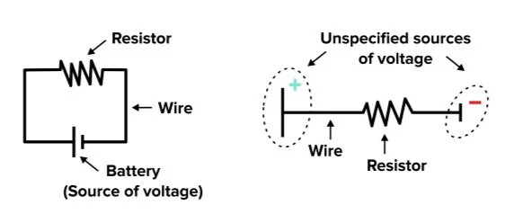
Figure 9 Two representations of circuits.
a) Voltage and electromotive force
For charge to move across a wire, there must be a difference in the electric potential between two points on it. This is similar to how a ball requires a difference in elevation to start rolling. The ball cannot spontaneously start rolling on level ground, and charge cannot spontaneously flow if there is no difference in potential.
Voltage is the difference in electric potential between two points on a circuit. It is typically given in volts (V).
In many circuits, the source of voltage is a battery. The battery converts chemical potential into electric potential. This action of converting non-electric energy into electric energy is called the electromotive force (EMF) of the battery. Despite the name, the electromotive force is not actually a force—it is simply the energy given to the charges inside of it. EMF is given in Joules per coulomb, a unit equivalent to volts.
Internal resistance refers to the material constraints of the battery that provide resistance and make it harder for the battery to produce voltage. However, if there is no internal resistance—as is often the case in MCAT problems—the EMF is the same as the voltage across the whole circuit.
An induced voltage is a voltage caused by a change in magnetic flux through a loop of wire over a change in time.
A voltmeter measures the voltage across a certain section of wire. It is placed in parallel with the section in question, and an ideal voltmeter has infinite resistance.
b) Current
If a voltage exists across a wire, negative charges will flow. This flow is called the current. Similar to a current of water in a river stream, electrical current is the rate of flow of charge past a given point.
I = ΔQ/Δt
where I = current,
ΔQ = the amount of charge that passes through,
Δt = the time elapsed
Electric current is given in units of coulombs per second. One coulomb per second is equivalent to one ampere (A).
Recall that positive charges are held by protons, which are large subatomic particles embedded in the nucleus. In a wire, the charges that are actually free to move are the electrons, which are small subatomic particles that are free to move. However, by convention, current is described as the movement of positive charges from high electric potential to low electric potential.
Current must be the same at all points along a single wire. However, different segments of wire within the same circuit may possess different values of current.
An ammeter measures the current of a wire. It is placed in series with the section of wire that must be measured. Importantly, an ideal ammeter has zero resistance—meaning that it does not impede the flow of electrons at all.
Conductivity is a measure of how easy it is for current to flow through a material. Perhaps intuitively, it is the inverse of resistivity:
σ = 1/ρ
where σ = conductivity,
ρ = resistivity
In most cases, metals are used as conductors because they can pass along the most current. Metallic conductivity is the result of the presence of unbound valence electrons in metals. These electrons can then travel between atoms.
An electrolytic solution will also conduct electricity. Electrolytic solutions are typically composed of salts dissolved in an aqueous solution to produce charged ions.
c) Resistance
It’s harder for charge to flow through some materials than through others. Imagine water flowing in a pipe. When a pipe narrows, it becomes more difficult to pass the same amount of water through the constriction. The same idea can be applied to circuits, where electrons flowing through a circuit encounter areas of high resistance. The resistance of a circuit quantifies how difficult it is for current to flow through it.
Note that like in a pipe, the resistance of a section of wire is proportional to the length of wire and inversely proportional to its cross-sectional area. The formula for the resistance of some section of wire is:
R = ρ × l/A
where R = the resistance,
l = the length of the segment of wire,
A = the cross-sectional area of the segment of wire,
ρ = the resistivity of the material
All circuits need resistors, which are circuit components that have particularly high resistances. The resistance of wires used in circuits is typically very low. Without dedicated resistors to control the amount of current that can flow, the current may become too high for the wire to tolerate, resulting in wire burnout.
How can we find the resistance of an entire circuit? If there is only one resistor present, finding the equivalent resistance is quite easy: it is simply the resistance of the sole resistor. However, more complex circuits will have multiple resistors that are placed in series or in parallel.
Resistors are in series with each other if they are directly connected by a wire. Thus, these resistors experience an identical current.
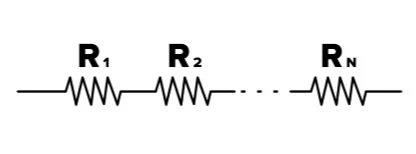
Figure 10 Resistors in series.
The equation for the total resistance, or equivalent resistance, is
RT = R1 + R2 + ... + RN
where RT = the equivalent resistance,
R1...RN = some number of resistors, labeled 1 through N
Note that when resistors are added in series, the equivalent resistance is higher than that of any individual resistor.
When resistors are in parallel, the wires have branched into two or more additional wires. Each branch contains its own resistor. Each of these resistors have differing currents passing through them; together, these values for current add up to the total current in the wire before the split.
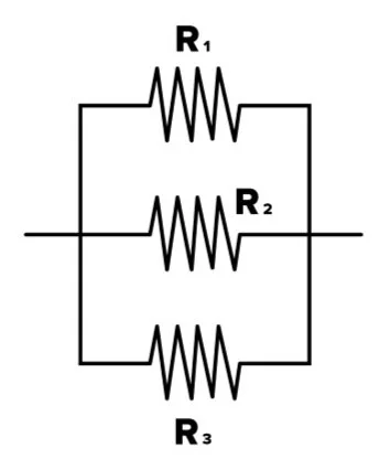
Figure 11 Resistors in parallel.
To find the equivalent resistance of resistors in parallel, use the following equation:
1/RT = 1/R1 + 1/R2 + ... + 1/RN
where RT = the equivalent resistance,
R1...RN = some number of resistors, labeled 1 through N
Notice that placing a resistor in parallel with another decreases the total resistance. Conceptually, this is due to the opening of additional “paths” for electrons to flow through.
d) Ohm’s law
Voltage, current, and resistance are related to each other by Ohm’s law:
V = I × R
where V = voltage,
I = current,
R = total resistance
This is true for any section of a circuit, as well as the entire circuit. Current is directly proportional to voltage and inversely proportional to resistance. Ohm’s law can be used to solve for any of these variables, so long as the other two are provided.
The electric power generated within a circuit can be given by a related equation:
P = I × V
where P = electrical power,
I = current,
V = voltage
Be aware that depending on the circuit, various segments of the circuit may experience different quantities of current or resistance.
e) Capacitors
Capacitors are devices used to temporarily store charge. They are produced from two conducting sheets that are very close to each other but not touching. Unlike batteries, which use chemical energy to produce differences in charge, capacitors use the physical separation between charges to store energy.
When the circuit is first active, a positive charge builds on the first plate. The repulsive electric field generated by this plate drives positive charge out of the second plate, leaving only the negatively charged particles. When enough charge is on the plates for the magnitude of the voltage in the capacitor to equal the voltage from the source, the current will stop.
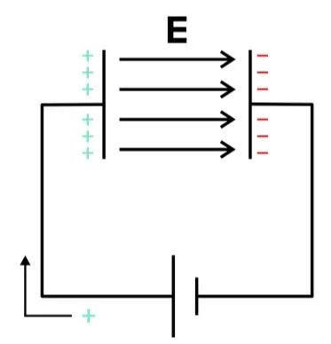
Figure 12 A parallel-plate capacitor.
Capacitance measures the ability of a capacitor to store charge. It is determined by the physical characteristics of the capacitor.
Parallel plate capacitors are the most common form of capacitor. As the name implies, these capacitors are composed of two identical, conductive plates that are arranged parallel to each other. Their capacitance is given by
where C = capacitance,
A = area of one of the plates,
d = distance between the plates,
ε0 = permittivity of space = 8.85 × 10⁻¹²,
k = relative permittivity of the material between the plates
As you might expect, parallel plate capacitors are better at storing charge if they are larger and closer together.
A “charged” capacitor can also provide the capacitance of the capacitor. The charge stored on the capacitor and the voltage in the circuit can be divided to provide the capacitance:
C = Q/V
where C = capacitance,
Q = charge stored on the capacitor,
V = voltage across the capacitor
Capacitance is measured in farads (F). One farad is an immensely large unit of stored charge—so most real-world circuit components use units of microfarads (µF).
Notice that a parallel plate capacitor’s capacitance depends on a factor of k. This factor quantifies the ease with which the electric field can move between the two plates. If there is a vacuum or air between the plates, k=1. Other materials have different values for k. Materials that are placed in between the plates of a capacitor are called dielectrics.
Dielectrics must be insulators (not conductors). Otherwise, the two plates of the capacitor would be electrically connected and current would flow. Although charge cannot flow through dielectrics, the molecules inside of them will rotate, or become polarized, to align with the electric field.
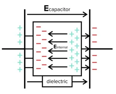
Figure 13 A dielectric within a capacitor.
Capacitors can be configured within circuits in many ways. As we discussed with resistors, capacitors may be inserted in a circuit in series or in parallel. It may also be useful to think of these multiple capacitors as an imaginary, larger capacitor with an equivalent capacitance. Importantly, the formulae for calculating equivalent capacitance are opposite from those for equivalent resistance.
For capacitors in series, the equivalent capacitance is given by:
1/CT = 1/C1 + 1/C2 + ... + 1/CN
For capacitors in parallel, the equivalent capacitance is given by:
CT = C1 + C2 + ... + CN
where CT = the equivalent capacitance,
C1...CN = some number of capacitors, labelled 1 through N
Note that when capacitors are placed in parallel, the equivalent capacitance is much higher than individual capacitors. Why is this? An analogous way of visualizing capacitors placed in parallel is to imagine a single, large capacitor with several lines cut across it. The capacitance of this “porous” capacitor is still directly proportional to the surface area on either plate.
To calculate the energy required to charge a capacitor up to a certain point, we must determine how much energy is stored in a capacitor with a given charge. To do so, use one of the following equations:
U = (1/2)Q2/C = (1/2)QV = (1/2)CV2
where U = energy stored in the capacitor,
Q = charge stored on the capacitor,
V = voltage across the capacitor,
C = capacitance of the capacitor
-----
Part 4: Magnetism
While electrostatics is the study of stationary charges, magnetism is the study of moving charges. Since magnetism is closely related to electrostatics, it may be helpful to understand the information we have covered so far before beginning to study magnetism.
a) Lorentz force
A magnetic field (or “B-field”) is a region of space in which a moving charge feels a force. The unit of magnetic field is tesla (T). This force is called the Lorentz Force and can be written as either a vector cross product or a scalar product. For simplicity, the scalar product (or magnitude of the vector product) is given below:
F = q × v × B × sinθ
where F = magnitude of the force on the charged object,
q = magnitude of the charge,
v = magnitude of velocity of the charge,
B = magnitude of the magnetic field,
θ = angle between velocity and magnetic field
Notice that due to the sine value, charges moving in the same direction as the magnetic field experience a force of zero Newtons.
This equation only provides the magnitude of the Lorentz force. To determine the direction, it will be helpful to use the right-hand rule.
The right-hand rule is a shortcut used to find the direction of vector cross products. Follow these steps to apply it to find the direction of the Lorentz force:
Point your index finger in the direction of the velocity.
Then, curl your middle finger in the direction of the magnetic field.
There should only be one orientation of your right hand that will allow this. In this orientation, the direction of your thumb will point in the direction of the Lorentz force.
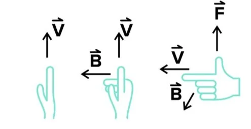
Figure 14 The right-hand rule.
When using the right-hand rule, be sure to use the right hand! Using the left hand will result in obtaining the opposite direction, and thus in an incorrect answer.
Notice that the Lorentz force is always perpendicular to both the velocity of a moving charge and the magnetic field. Thus, the acceleration of the moving particle is also perpendicular to its motion.
b) Magnetic field and current
How are circuits affected by a magnetic field? After all, a current in a wire is simply a collection of moving charges. It may not surprise you that lengths of wires that carry current can also experience forces from magnetic fields. The magnitude of these forces is given by:
F = I × L × B × sinθ
where F = force on the wire,
I = current in the wire,
L = length of the wire,
B = magnitude of the magnetic field,
θ = angle between current and B-field
The direction of the force is given by the same right-hand rule as the Lorentz Force: the only difference is that your index finger must point in the direction of current.
The relationship between B-fields and current is slightly more nuanced. Current-carrying wires not only feel forces in magnetic fields but can create magnetic fields themselves. The magnetic field created by a current is given by the Biot-Savart law, which, for a long straight wire, simplifies to:
B = μ0I/(2πR)
where B = magnetic field produced by the current,
μ0 = permeability of free space = 4π × 10−7,
I = current in the wire,
R = distance from the wire
The direction of this b-field is given by a sort of modified right-hand rule:
Point your right thumb in the direction of the current.
Then, curl your fingers into your palm.
Your fingers will point in the direction of the magnetic field. The magnetic field created by a current will point in directions that curve around the wire.
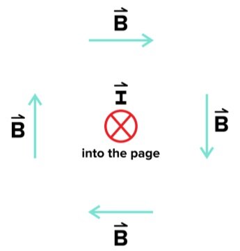
Figure 15 A B-field generated by a wire that extends into the page.
A solenoid is a current-carrying coil of wire. Solenoids are remarkable in that they create an approximately uniform b-field inside of them. We can use another form of the right-hand rule here: if you curl your fingers in the direction of the current, your thumb will point in the direction of the magnetic field. This works for any loop of current.
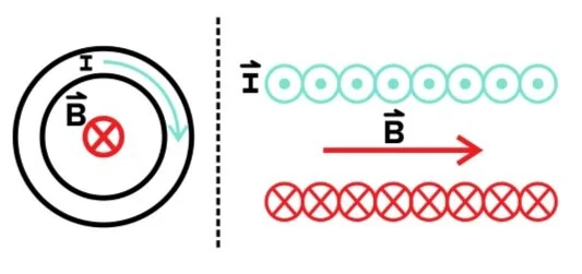
Figure 16 B-field produced by a loop of wire (solenoid).
Let’s see how this applies to induced voltage. The equation for an induced voltage is given by:
ε = −ΔΦ/Δt
where ε = induced voltage on the loop,
ΔΦ = change in magnetic flux through the loop,
Δt = change in time
Magnetic flux is the amount of magnetic field that goes through a loop. It is simply given by the magnetic field times the area of the loop:
Φ = B × A
The negative sign in this equation indicates that loops of wire oppose changes in magnetic flux. Think of it this way: the loop seeks to maintain its initial magnetic flux, so when the magnetic flux changes, the loop creates its own magnetic field to oppose the change in flux. If the flux decreases, for example, the loop will gain a current that restores some of that flux. This induced current tells you that there is an induced voltage, too.
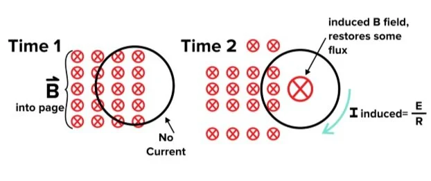
Figure 17 Induced voltage due to magnetic flux
Additionally, the induced voltage is proportional to the rate of change of magnetic flux. So, when comparing the same change in flux in two different loops, the change that occurs over a shorter period of time will induce a larger voltage.
-----
Part 5: High-yield terms and equations
Electrostatics: the study of electromagnetic phenomena of stationary charges
Charge: the physical property of matter that causes it to feel a force in an electric field
Elementary charge: proton or electron; the smallest possible units of charge; 1.6 x 10^(-19) C
Charge conservation: charge is neither created nor destroyed; it only moves around
Coulomb’s law: the force between two charges
Electric field: a region in which a charge will feel a force
Field lines: a collection of straight arrows used to represent electric fields
Induced charge: a charge distribution resulting from placing a conductor in an electric field
Conductor: a material that allows charge to move freely
Electric potential: the amount of work needed to move a charge a certain distance inside of an electric field
Electric potential energy: the potential energy of a charge inside of an electric potential
Equipotential lines: the contour lines of the electric potential
Circuit: a closed path that allows current to flow from one place to another
Voltage: a difference in potential between two points in a circuit
Electromotive force: the action of converting non-electric energy into electric energy
Internal resistance: the material constraints of the battery that make it hard to produce voltage
Induced voltage: a voltage caused by a change in magnetic flux through a loop of wire over a change in time
Electrical current: the rate of flow of charge past a given point
Resistance: how hard it is for current to flow through a material
Resistivity: property of a material that determines the resistance of a piece of that material
In series: when circuit components are directly connected by a wire and share a current
In parallel: when circuit components are on alternate branches of wire and share a voltage
Equivalent resistance: a single resistance equivalent to the combination of all resistances in the circuit
Equivalent capacitance: a single capacitance equivalent to the combination of all capacitances in the circuit
Ohm’s law: law that says current is directly proportional to voltage and inversely proportional to resistance
Capacitors: devices used to store charge
RC circuit: a circuit with a capacitor
Capacitance: the ability of a capacitor to store charge
Dielectrics: materials that are placed in between the plates of a capacitor
Ammeter: device that measures the current of a wire
Voltmeter: device that measures the voltage across a certain section of wire
Conductivity: a measure of how easy it is for current to flow through a material
Metallic conductivity: conductivity resulting from the presence of unbound valence electrons in metals
Electrolyte solution: conducting solutions made of polarized molecules that have been dissolved in water
Magnetism: concerns moving charges
Magnetic field: a region of space where a moving charge feels a force
Lorentz force: the force on a charge moving in a magnetic field
Right-hand rule: a shortcut used to find the direction of vector cross products
Biot-Savart law: gives the magnetic field created by a current
Solenoid: a current-carrying coil of wire
Equations
Coulomb’s law F = −kq1q2/r2
Force due to arbitrary electric field F = E × q
Electric potential V = E × d × cosθ
Electric potential energy UE = q × V
Electrical current I = ΔQ/Δt
Resistance R = ρ × l/A
Conductivity σ = 1/ρ
Ohm’s law V = I × R
Equivalence for components in series RT = R1 + R2 + ... + RN
1/CT = 1/C1 + 1/C2 + ... + 1/CN
Equivalence for components in parallel 1/RT = 1/R1 + 1/R2 + ... + 1/RN
CT = C1 + C2 + ... + CN
Capacitance C = Q/V
Parallel plate capacitance C = kε0A/d
Energy in capacitor U = (1/2)Q2/C = (1/2)QV = (1/2)CV2
Lorentz force (moving charge in b-field) F = q × v × B × sinθ
Force on wire in b-field F = I × L × B × sinθ
Biot-Savart law (b-field created by straight wire) B = μ0I/(2πR)
Induced voltage Ε = −ΔΦ/Δt
Permittivity of space ε0 = 8.85 × 10⁻¹²
Permeability of free space μ0 = 4π × 10−7
-----
Part 6: Passage-based questions and answers
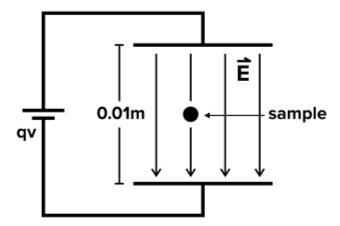
Figure 1
Researchers perform a second experiment to determine the mass of the molecule using a cyclotron. A cyclotron contains a tunnel with an electric field and magnetic field pointing in perpendicular directions across its width. A charged particle is ejected through the tunnel at a characteristic velocity. The electric field and magnetic field are oriented such that their exerted forces on the molecule sum to zero.
The particle then emerges from the end of the tunnel into a space where the magnetic field remains, but the electric field is turned off. Remaining under the force of the magnetic field, the particle undergoes circular motion and travels to a distance 2r from the opening of the tunnel.
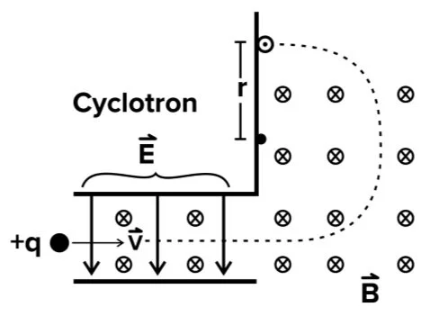
Figure 2
This passage was created for educational purposes only
Question 1: What is the charge of Molecule Alpha?
A) - 1.1 x 10⁻¹⁰ C
B) - 9.0 x 10⁻¹⁰ C
C) + 1.1 x 10⁻¹⁵ C
D) + 9.0 x 10⁻¹⁵ C
Question 2: At what velocity should a sample of 1010 molecules be fired into the tunnel of the cyclotron so that it will make it to the end of the tunnel?
A) v=E/B m/s
B) v=11×10-5*E/B m/s
C) v=11×10-5*B/E m/s
D) v=11×10-5*E m/s
Question 3: What is the acceleration experienced by the sample once it enters the space outside of the tunnel?
A) a = E2/(B2r)
B) a = E/(Br)
C) a = E/(B2r)
D) a = E2/(Br)
A) m = E/(qB2r)
B) m = qE/a
C) m = qrB2/E
D) m = qvB/a
1. Answer choice C is correct. According to the information presented in the passage, the molecule is pulled toward the negatively charged plate. Thus, the molecule must have a positive charge (choices A and B are incorrect). We can use the equation for electric field E = V/d, using the values of 9V and 0.01m to find E. We then plug this into our equation:
F = E × q
q = F/E = (1 × 10⁻¹²)/900 = 1.1 × 10⁻¹⁵ C
2. Answer choice A is correct. For the sample to escape the tunnel, the forces due to the electric field and the magnetic field must sum to zero. They must have equal magnitude. Thus,
E × q = q × v × B
E = v × B
v = E/B
3. Answer choice A is correct. We know that a charge moving in a magnetic field undergoes circular motion. The acceleration that causes circular motion is centripetal acceleration, which is given by a = v2/R. The distance 2r is the diameter of the circle, so the radius is simply r. From the derivation provided in question 3, v = E/B. After substitution, we find that:
a = v2/R
a = (E2/B2) × (1/r) = E2/(B2r)
4. Answer choice C is correct. Newton’s second law tells us that m = F/a. Further, we know that the force experienced by the particle is the Lorentz force, which is given by:
F = q × v × B
Additionally, v = E/B and a = E2/(B2r). Thus, we can manipulate these equations to obtain:
m = F/a
m = (q × v × B)/a = (q/1) × (E/B) × (B/1) × (B2r/E2) = qrB2/E
-----
Part 7: Standalone questions and answers
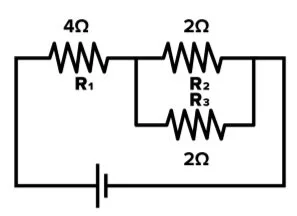
Question 1: What is the equivalent resistance of the circuit below?
A) 4 Ohms
B) 5 Ohms
C) 6 Ohms
D) 7 Ohms
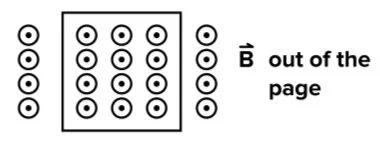
Question 2: If the b-field below is turned off, in what direction will the current flow?
A) Clockwise
B) Counterclockwise
C) No current will flow
D) There is not enough information to form a conclusion
Question 3: Two long wires of length L are oriented parallel to each other at distance d and experience currents I1 and I2. What is the force exerted by one wire on the other?
A) F = q × I × B/d
B) F = μ0I1I2/L
C) F = μ0I1I2L/(2πd)
D) F = 2πd/(μ0I1I2L)
Question 4: What is the voltage across a capacitor in an RC circuit connected to a 9V battery instantaneously after the circuit is switched on?
A) 0 V
B) 3 V
C) 6 V
D) 9 V
Question 5: A neutrally charged conductor is brought close to (but does not touch) a negatively charged point charge. At what point does the conductor have the greatest total charge?
A) Before it is brought close to the point charge
B) When it is close to the point charge
C) When it is taken away from the point charge
D) None of the above
Answer key for standalone questions
1. Answer choice B is correct. When simplifying complex circuits, it is often helpful to begin with the simplest components. In this case, the simplest subsection consists of the two 2 Ohm resistors placed in parallel with each other.
1/R2,3 = 1/R2 + 1/R3 = 1/2 + 1/2 = 1 Ω
After calculating this equivalent resistance, we can treat it as the resistance of a component that is in series with the 4 Ohm resistor of R1.
RT = 1 + 4 = 5 Ω
2. Answer choice B is correct. The relevant equation is:
ε = −ΔΦ/Δt = −(ΔB × A)/Δt
The B-field points out of the page, so the magnetic flux does as well. When the B-field is turned off, the loop will oppose the loop of the flux—so a current that creates a magnetic field out of the page will be induced. Using the right-hand rule, we see that the current must flow counterclockwise (choice B is correct).
3. Answer choice C is correct. The force on a wire due to a magnetic field is F = I × L × B × sin(θ). A magnetic field generated by a current rotates around the wire, so it will be perpendicular to a parallel current, implying that θ = 90 degrees and sin(θ) = 1. The magnitude of the magnetic field due to a current is:
B = μI/(2πd)
When we rearrange these expressions, we obtain:
F = I × L × B
F = I × L × (μI/(2πd)) = μI1I2L/(2πd)
4. Answer choice A is correct. Instantaneously after the circuit was just switched on, current has just started to flow, meaning that there has not been a buildup of charge on the plates of the capacitor. This means there is no electric field between the plates, and thus, there is no potential difference from one plate to the other (choice A is correct).
5. Answer choice D is correct. Although the charges inside the conductor will become redistributed when it is close to the point charge (thus becoming polarized), the charge of the two poles will always sum to zero due to the conservation of charge. The net charge of the conductor will not change unless it actually touches the point charge, thus allowing negatively charged electrons to transfer (choice D is correct).
Not ready to commit to your MCAT prep at this time?
Enter your name and email for a free MCAT question delivered straight to your inbox daily.