
Master MCAT light and optics concepts with clear explanations of reflection, refraction, lenses, mirrors, diffraction, and high-yield practice questions.

(Note: This guide is part of our MCAT Physics series.)
Table of Contents
Part 1: Introduction to light and optics
Part 2: Characteristics of light
Part 2: Characteristics of Light
a) Photons
b) Double- and single-slit experiments
c) Reflection, refraction, and Snell's law
d) Additional phenomena
Part 3: Mirrors
a) Flat mirrors
b) Spherical mirrors
Part 4: Thin Lenses
a) Convex and concave lenses
b) Combining lenses
Part 5: High-Yield Terms and Equations
Part 6: Passage-Based Questions and Answers
Part 7: Standalone Questions and Answers
-----
Part 1: Introduction to light and optics
In this guide on light and optics, we will study the characteristics of light: including its trajectory and propagation. Light and optics are important for light-related reactions and many precision instruments you might find in a lab. For this reason, it is considered to be a medium-yield topic on the MCAT. In all likelihood, when it does come up on the MCAT, it will be in a strictly biological context as opposed to the physics and mathematical contexts in the sections below. However, understanding the fundamentals of this field will make understanding light and optics in relation to biology much smoother.
Receive Your Free MCAT Question of the Day
Get every last bit of practice in before test day with a free MCAT question delivered straight to your inbox daily.
-----
Part 2: Characteristics of light
Light is an electromagnetic wave of any wavelength. The electromagnetic spectrum—and therefore, what can be categorized as light waves—includes waves of all wavelengths, from radio frequencies to x-rays. Visible light, the light that makes up all the colors you see, only includes light in a small range of wavelengths (about 400-700 nanometers).
a) Photons
Recall that an electromagnetic wave is a wave composed of perpendicularly oscillating electric and magnetic fields. The two fields interact with each other and propagate light in the direction perpendicular to both oscillations.

Figure 1 Light is an electromagnetic wave.
However—perhaps the biggest “however” in physics—light can also be understood as a particle instead of a wave. A photon is a massless particle that represents a discrete unit (or a “quantum”) of light. We will use photons as a representation of light when considering the energy absorbed from light striking an object.
When objects absorb energy from incident light, they can only do so in discrete amounts. This discretized unit is called the photon energy. It is proportional to the frequency of light.
E = h × f
where E = photon energy,
f = frequency,
and h = Planck's constant, 6.63 × 10⁻³⁴ J · s
Note that frequency and wavelength are inversely proportional: or that
λ = ν/f
where λ = wavelength,
ν = the speed of light,
and f = frequency
Thus, light with high-frequency wavelengths has more energy than light with low-frequency wavelengths.
If the wave-particle duality of light doesn’t sit well with you, that’s completely fine! It is a debate that continues to puzzle many physicists today. This information is simply meant to prepare you for the different representations of light that will come later. Some applications will treat light as a wave, and others as a linearly moving particle.
b) Double- and single-slit experiments
All forms of waves share some similarities in their behavior. Interference occurs when two waves collide and combine. Constructive interference occurs when waves are in phase, and sum to make waves with a larger amplitude. Destructive interference occurs when waves are out of phase and cancel each other out to form a wave with zero amplitude. (For more information on this, be sure to refer to our guide on waves and sound.)

Figure 2 Two waves of equal amplitude traveling in opposite directions exhibiting constructive interference.

Figure 3 Two waves of opposite amplitude traveling in opposite directions exhibiting destructive interference.
As light can be considered as a wave, they also exhibit interference. This phenomenon was first observed during Thomas Young’s double-slit experiment. The results of this experiment led scientists to believe that light behaves as a wave.
In the double-slit experiment, light is shone through two narrow slits placed close together. After passing through the slits, the light strikes a wall and shows alternating bright spots and shadows—a pattern indicative of interference. The “maxima,” or bright spots, are areas of constructive interference. The “minima,” or shadows, are areas of destructive interference.

Figure 4 The double-slit experiment.
The following equation determines where these maxima and minima will occur:
d × sinθ = m × λ
where d = distance between the slits,
θ = angle (from horizontal) to a location on the wall,
m = a numerical multiple,
and λ = wavelength of the incoming light
Take a moment to match the different terms in the equation to the image above it. While you won’t be expected to apply this equation on the MCAT, it’s useful to understand each variable.
Note that for any interference to occur, the light sources must be coherent, meaning the waves are in-phase. This is satisfied in the double-slit experiment because the light coming through each slit is generated by the same source and therefore must maintain the same phase relationship and amplitude. The other condition for interference is that the light must be monochromatic, meaning it consists of only one frequency or color.
What happens when we change the orientation of these two slits? A screen with many slits evenly spaced and placed close together is called a diffraction grating. The bright spots and dark spots from a diffraction grating are more intense, and the transition between them is more abrupt. The bright spots are relatively narrow, while the dark spots are wider.
In contrast to the double-slit experiment, in the single-slit experiment, light is shone through a single slit. Since there is only one slit, only one beam of light is allowed through. The waves of light passing through this slit are still able to constructively and destructively interfere with each other. The resulting diffraction pattern from a single slit appears to be more generally dispersed than the pattern resulting from a double slit.
c) Reflection, refraction, and Snell’s law
Light interacts with solids and objects in different ways. Reflection occurs when light bounces off of a surface. There are two types of reflection: specular reflection and diffuse reflection.
Specular reflection occurs when light reflects off a smooth surface at a definite angle. The simplest form of specular reflection occurs when light is shone perpendicularly at a surface. After it hits the surface, it is reflected back in the same direction it came from.
When light is shone at an angle, the same concept is at work. To understand this, decompose the initial vector of light into two components. After the reflection, the component pointing perpendicular to the wall reverses its direction. The component pointing parallel to the wall stays the same.

Figure 5 Reflection reverses the component of light perpendicular to the wall.
A simpler way to think about this is to say that the angle of incidence equals the angle of reflection. (Note that these angles are both measured with respect to the dashed perpendicular line.)

Figure 6 The angle of incidence is equal to the angle of reflection.
Diffuse reflection occurs when light bounces off a rough surface. The light penetrates into the microscopic crevices of the surface before undergoing normal speculative reflection. Since the microscopic surfaces face in essentially random directions, light reflects off the surface in all directions—rather than just the one that preserves the initial angle of incidence.

Figure 7 Diffuse reflection results in light being reflected at many angles.
These two forms of reflection explain why mirrors and white pieces of paper don’t appear to be the same. They both reflect all wavelengths of visible light. However, mirrors cause specular reflection that preserves the shape and location of incident light, while white pieces of paper only reflect white light in a diffuse manner.
In contrast to the behavior of light when it strikes a solid surface, light engages in refraction when it passes through different mediums.
n = c/v
where c = the speed of light in a vacuum,
v = speed of light in a new medium
Note that this implies that n must always be greater than 1, as light cannot travel faster than it does in a vacuum (or v cannot be larger than c). However, it is fine to approximate the refractive index of air as 1, as the speed of light in air is nearly identical to the speed of light in a vacuum.
You may be familiar with refraction in your everyday life. Consider a drinking straw placed in a glass of water. When light is shone perpendicularly through the glass, it will continue to travel straight through the glass at a lower velocity. However, if the light hits the glass at an angle, things become more complicated. The proportion of light’s velocity components changes, which means that the light—and the straw it has reflected off of—appears to “bend.”
When light crosses from one material to another, this apparent “bending” is described by Snell’s law,
n1 × sinθ1 = n2 × sinθ2
where n1 = the index of refraction of the first material,
θ1 = the angle of incidence (from the normal),
n2 = the index of refraction of the second material,
θ2 = the angle of refraction (from the normal)

Figure 8 The quantities involved in Snell's law.
n1/n2 = sinθ2/sinθ1
Materials such as water and glass usually transmit much of the light incident on them. However, at certain angles of incidence, a ray of light won’t penetrate them at all and will instead just skip off the surface. In these cases, all of the incident light is reflected—even by materials that may be transparent or translucent. This phenomenon is called total internal reflection.
n1 × sinθc = n2 × sin(90°)
where n1 = the index of refraction of the first material,
θc = the critical angle (measured from the normal),
n2 = the index of refraction of the second material
d) Additional phenomena
Recall that light is an electromagnetic wave. Different wavelengths correspond to different types of light. Red light has a longer wavelength than blue light, which has a longer wavelength than x-rays.
As it turns out, the speed of light in some materials depends on the wavelength. Light of different wavelengths or different colors has different indices of refraction. The shorter the wavelength, the more the light will bend.
The result of these different refraction indices is dispersion. Different wavelengths of light will separate themselves and spread out when they enter a new material.

Figure 9 A rainbow appears in a prism due to the dispersion of white light.
You’ve probably seen a rainbow on a rainy day. This is the direct result of dispersion. When sunlight shines through water in the air—changing between mediums—it’s separated into its different colors. The separation of these colors always follows the same arrangement, with visible light being arranged from longest wavelength to shortest.
In addition to dispersion—the same phenomenon at work in the single-slit, double-slit, and diffraction grating experiment—it may also be helpful to understand some additional light-related phenomena.
X-ray diffraction is a technique for determining the atomic or molecular structure of a material. Most commonly, x-rays are shot at crystals in order to determine the specific crystal structure.
Thin-film diffraction is responsible for the rainbow patterns you can see in oily water or in soap bubbles. Thin films are translucent. They reflect some light with their outer boundary and let the rest penetrate to the far boundary, where similarly reflected. Because the distance between each boundary is so small, the different pools of reflected light interfere with each other, causing regions of bright and dark colors.
Opacity is the measure of light’s ability to penetrate a given object or the ability of an object to transmit light.
If an object allows all light to pass through it, it is transparent.
If an object allows some light to pass through it, it is translucent.
If an object allows no light to pass through it, it is opaque.
Lenses, such as a magnifying glass, are effectively transparent and transmit all incident light. Mirrors are opaque and transmit no light, meaning they reflect or absorb all incident light.
Light polarization describes the organization of individual light waves. We know that a single light wave is a wave composed of perpendicularly oscillating electric and magnetic fields. Separate light waves, however, don’t need to maintain any specific orientation with respect to one another. They are usually just randomly oriented. When they are organized in a way that aligns the oscillations, they are polarized. That is, polarized light is light in which the electric field is oscillating in only one plane. There are several methods of polarizing light.
Selective absorption is a technique that uses a polarizer to filter out light that is not polarized in a certain direction.
Double refraction occurs when a material’s index of refraction depends on the polarization of light. When randomly polarized light is transmitted through this material, it splits into differently polarized beams of light.
Scattering light off air molecules produces polarized light.
Polarizing angles are angles at which all reflected light is polarized.
Optically active molecules rotate incident light. Understanding optical activity requires an understanding of stereochemistry: all optically active molecules are chiral, while not all chiral molecules are optically active.
The Doppler effect describes a change in the frequency of a wave that is the result of a relative motion between a wave source and its observer. We’ve discussed the application of the Doppler effect as it relates to sound in other guides, but the Doppler effect applies to light as well.
Imagining this with light can be tricky, so let’s begin with a more concrete example. Imagine a train is hurtling past you with a frequency of 1 train car per second. If you start driving your car at the same speed as the train but in the opposite direction, two train cars will pass you in one second. Eventually, you pass the train depot and find yourself driving alongside a train going in the same direction as you. Since you are going the same speed as this train, no train cars pass you in one second. Although each train is traveling at the same speed, you observe different frequencies in the car because of your motion.
An analogous system involves a light emitter—say, a star in space—traveling at some velocity away from you, the observer. In this system, the source is moving instead of the observer, but the result is the same. If the star is traveling towards you, there is a blueshift: the frequency seems to be higher than it really is. If the star is traveling away from you, there is a redshift: the frequency seems lower than it really is. Since everything in the universe is always moving, these are fundamental concepts in astronomy.
The equation for the Doppler effect is:
f′ = ((c + v0)/(c − vs)) × f
where f′ = observed frequency,
c = the speed of light,
v0 = speed of the observer,
vs = speed of the source,
f = actual frequency
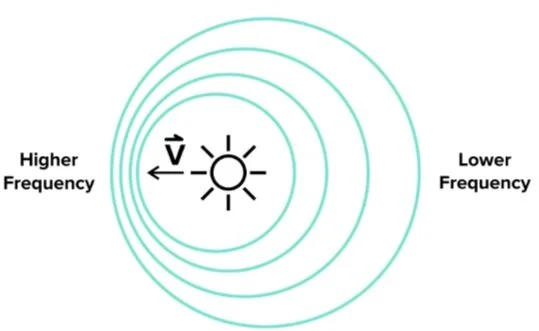
Figure 10 The Doppler effect.
-----
Part 3: Mirrors
Mirrors are tools that perfectly reflect light because they are opaque and smooth. Mirrors come in three basic shapes, each of which exhibits different kinds of reflection.
a) Flat mirrors
Flat mirrors, or plane mirrors, reflect all incident light in the same way. This preserves the distance between objects and creates an image that appears to be a representation of real life. As a result, flat mirrors are the most common type of mirror you might encounter in everyday life.
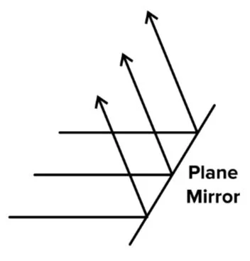
Figure 11 A plane mirror.
When mirrors are curved, they do not reflect all incident light the same way. Curved mirrors can be either concave or convex.
Concave mirrors focus on incident light. In other words, incident light converges after being reflected. The point where the uniform field of light converges is called the focal point.
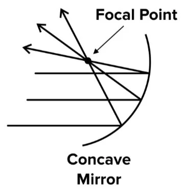
Figure 12 A concave mirror.
Convex mirrors do not focus light. Any incident light that is reflected by the convex mirror will diverge away.
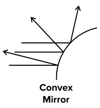
Figure 13 A convex mirror.
Mirrors with circular curvature in two dimensions are called spherical mirrors. Spherical mirrors cause convergence or divergence in the exact same way as the mirrors in the diagrams above. However, spherical mirrors cause convergence and divergence in the vertical direction in addition to the horizontal direction.
b) Spherical mirrors
Let’s take a deeper look at spherical mirrors. We are mostly interested in the focal length of a mirror, its magnification, and the relationship between the two.
Spherical mirrors are also important because they are directly analogous to thin lenses. We’ll cover the behavior of thin lenses in the next section.
There are several geometric relationships that we will need to establish. The diagram below shows some quantities that will be important to understand.
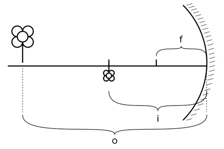
Figure 14 Image distance, object distance, and focal length for a concave mirror.
An object is any real-life object that is observed with a mirror or lens. In the above diagram, the object is represented by an upright flower.
An image is a reflection that is created by a mirror or the resulting distortion caused by a lens. Curved mirrors at carnivals can make you look tall and thin, short and round, and curved out of proportion in any number of ways. That is, the image you see in the mirror is a distorted version of the object (you!).
The distances of the object and image to the lens or mirror in question will become very important. By convention, the distance from the image to a mirror is denoted i, and the distance from the object to a mirror is denoted o.
The focal length, denoted f, is a property of the spherical mirror itself. It is equal to one-half the radius of curvature, or the radius the spherical mirror would be if it extended into a complete sphere:
f = R/2
where f = focal length,
R = radius of curvature
Further, the focal length can be related to the image and object distances through the following equation. This means that you should be able to solve for the third variable in the equation when provided any of the other two.
1/f = 1/i + 1/o
where f = focal length,
i = distance from image to mirror,
o = distance from object to mirror
There are some key differences between convex and concave mirrors. These differences, and the resulting sign conventions, are shown in the table below.
Table 1 Concave vs convex mirrors
| Convex mirror | Concave mirror |
|---|---|
Real images are formed by focus points of converging light rays. They are always inverted. Objects that are reflected by concave mirrors or convex lenses have real images.
Virtual images are formed by inferred focus points of diverging light rays. They are not inverted. Objects that are reflected by convex mirrors or concave lenses, or are within one focal length of a concave mirror or convex lens, have virtual images.
Note that by comparing the image and object distances, we can also compare the height of the object to the resulting height of the image. This is due to the similar triangles that are formed by the reflected light rays.
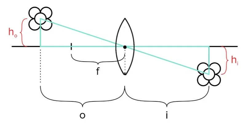
Figure 15 Similar triangles formed between image and object distance and height, as formed by a concave mirror.
The derivation of this relationship is beyond the scope of the MCAT. For the exam, it’s sufficient to understand that
i/o = hi/ho
style="text-align: left;" This gives us a relationship that is equivalent to the resulting magnification of a mirror or lens. Magnification is the ratio of the image produced by an optical device and the object’s true size.
M = h′/h = −i/o
where M = magnification,
h′ = height of the image,
h = true height of the object,
i = distance from image to mirror,
o = distance from object to mirror
-----
Part 4: Thin lenses
Lenses are optical devices that allow light to pass through them. They must be curved, and, like mirrors, they change the direction of light rays that pass through them. Like mirrors, these changes in direction result in the formation of images. Lenses also have characteristic focal lengths, which are denoted as f, and produce images at a distance i.
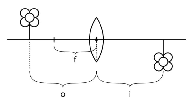
Figure 16 A depiction of focal length, object distance, and image distance formed by a convex lens.
a) Convex and concave lenses
Convex lenses are like concave mirrors. They cause light to converge at a single point that is located one focal length away from the mirror.
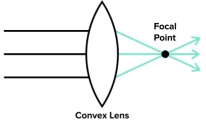
Figure 17 A convex lens.
Note that the image formed by a convex lens is real, as the image is where you would expect it to be: formed on the opposite side of the lens. This means that the image distance is positive, and the object distance is positive.
In the same vein, concave lenses are like convex mirrors. They cause light to diverge.
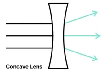
Figure 18 A concave lens.
However, for a concave lens, the virtual image is on the same side of the lens as the object. This means that the image distance is negative, and an upright and virtual image is formed.
The sign conventions and differences between convex and concave lenses are outlined in the table below:
Table 2 Convex vs concave lenses
| Convex lens | Concave lens |
|---|---|
Just as with mirrors, we can derive a relationship between the image and object distance and height.
Figure 19 Similar triangles formed between image and object distance and height, as formed by a convex lens.
The equations for mirror magnification and focal length remain the same for thin lenses:
M = h′/h = −i/o, and
1/f = 1/i + 1/o
where f = focal length,
i = distance between the image and the lens,
o = distance between the object and the lens
The strength of a lens measures its capacity to make light converge or diverge. In other words, the strength of a lens measures how short the focal length is. Lens strength is measured in diopters.
P = 1/f
where P = lens strength (in diopters),
f = focal length (in meters)
Note that the standard unit of measurement for focal length is in meters—rather than centimeters.
Just like with mirrors, you may be expected to calculate any of these quantities. You should be familiar with manipulating these equations and working with fractions. For additional practice with fractions, refer to our guide on MCAT math.
A popular application of convex lenses on the MCAT is in analyzing visual disorders. Recall that the lens of the eye is a form of convex lens. (For more information on visual sensation, refer to our guide on consciousness, sensation, and perception.) If the lens is warped such that the image distance is too short (e.g., an image is formed in front of the retina), an individual is said to have short-sightedness. This is also referred to myopia. In contrast, if the lens is warped such that the image distance is too long (e.g., an image is formed behind the retina), an individual is said to have far-sightedness. This is also referred to as hyperopia.
Typically, patients with short-sightedness are able to see nearby objects clearly, but objects in the distance appear blurry. The reverse is true for far-sightedness: patients with this condition can see distant objects clearly, but nearby objects appear blurry.
b) Combining lenses
Solving for unknown variables in systems of combined lenses isn’t much more complicated than systems of single lenses. To do so, simply use the real image of the first lens as the object for the second lens. Similarly, the collective magnification of multiple lenses is just the product of all the individual magnifications.
Note that in this entire guide, we’ve assumed that we’re dealing with perfect lenses. More realistic lenses exhibit lens aberration, which means that their focal length is less precise. Light rays that pass through these more realistic lenses converge at slightly different distances.
-----
Part 5: High-yield terms and equations
Light: an electromagnetic wave of any wavelength
Visible light: the light you can see, at wavelengths of about 400-700 nm
Electromagnetic wave: a wave that is made of perpendicularly oscillating electric and magnetic fields
Speed of light: the speed at which light travels in a vacuum; equal to 3 x 10^8 m/s
Photon: a massless particle that represents a discrete unit (or a “quantum”) of light
Wave-particle duality: light exhibits properties of both particles and waves
Opacity: the measure of light’s ability to penetrate a given object, or the ability of an object to transmit light
Transparent: describes an object that allows all light to pass through it
Translucent: describes an object that allows some light to pass through it
Opaque: describes an object that allows no light to pass through it
Reflection: when light bounces off of a surface
Specular reflection: when light reflects off a smooth surface at a definite angle (equal to the angle of incidence)
Angle of incidence: the angle at which a ray of light hits a surface
Angle of reflection: the angle at which a ray of light is reflected off a surface
Diffuse reflection: occurs when light bounces off a rough surface at a random angle
Index of refraction: the extent to which a material bends light that it transmits
Snell’s law: determines the angle of refraction at a boundary between two materials
Total internal reflection: when the angle of incidence is small enough for all light to be reflected
Critical angle: the smallest possible angle (from vertical) at which total internal reflection occurs
Dispersion: the organized separation of different frequency light due to frequency-dependent indices of refraction
Mirror: an object that perfectly reflects light
Plane mirror: a flat mirror that produces specular reflection and preserves the position of reflected images
Concave mirror: a mirror that focuses, or makes converge, incident light
Focal point: the point at which a uniform field of light is focused by a concave mirror
Convex mirror: a mirror that scatters, or makes diverge, incident light
Spherical Mirror: a mirror that has circular curvature
Center of Curvature: the point equidistant from all points on the spherical mirror
Real image: an image formed by the focus points of converging light. Always inverted
Virtual image: an image formed by inferred focus points of diverging light rays. Not inverted
Magnification: how much an optical device changes the apparent size of an object
Focal length: the distance between the center of a curved mirror and its focus point
Lens aberration: the imprecision of focal lengths of realistic lenses
Photon energy: the discretized unit of light energy absorbed by objects
Constructive interference: when waves are in phase and combine to make a larger wave
Destructive interference: when waves are out of phase and cancel out
Coherent: describes light sources that maintain the same phase relationship
Monochromatic: Describes light that is only one color or frequency
X-ray diffraction: a technique for determining the atomic or molecular structure of a material
Polarized light: light whose electric fields all oscillate in the same plane
Selective absorption: a technique that uses a polarizer to filter out light that isn’t polarized in a certain direction
Polarizing angles: angles at which all reflected light is polarized
Double refraction: when a polarization-dependent index of refraction splits incident up into differently polarized beams of light
Optically active molecules: molecules that rotate incident light
Doppler effect: describes a change in frequency of a wave that is the result of a relative motion between a wave source and its observer
Blue shift: when a source traveling towards you makes the frequency seem to be higher than it really is
Red shift: when a source traveling away from you makes the frequency seem to be lower than it really is
Equations
Snell's law: n1 × sinθ1 = n2 × sinθ2
Magnification: M = h′/h = −q/p
Thin lens equation: 1/f = 1/p + 1/q
Lens strength: P = 1/f
Photon energy: E = h × f
Double-slit equation (applied to diffraction gratings): d × sinθ = m × λ
Single-slit equation: a × sinθ = m × λ
Doppler equation: f′ = ((c + ν0)/(c − νs)) × f
Speed of light: c = 3 × 10⁸ m/s
Planck's constant: h = 6.63 × 10⁻³⁴ J · s
-----
Part 6: Passage-based questions and answers
Contact lenses are highly useful when investigating the structure of the animal eye. Placing a soft contact lens on the eyeball prevents dehydration of the cornea and limits the effect of any naturally-occurring geometrical aberrations on the lens that may affect the resolution of a retinal image.
Researchers seeking to create low-cost, customizable contact lenses investigate a new procedure for creating and shaping hydrogel lenses. To do so, a solution was prepared by mixing 2-hydroxyethyl methacrylate with inhibitor removal beads. After filtering out the beads, a crosslinking agent, deionized water, and activator were stirred into the solution. The solution was poured into molds and round indentations were made with 6 mm ball bearings.
To test the functionality of these fabricated contact lenses, the indented sections of hydrogen were cut out and compared to industrially available contact lenses. The results are shown in Figure 1.
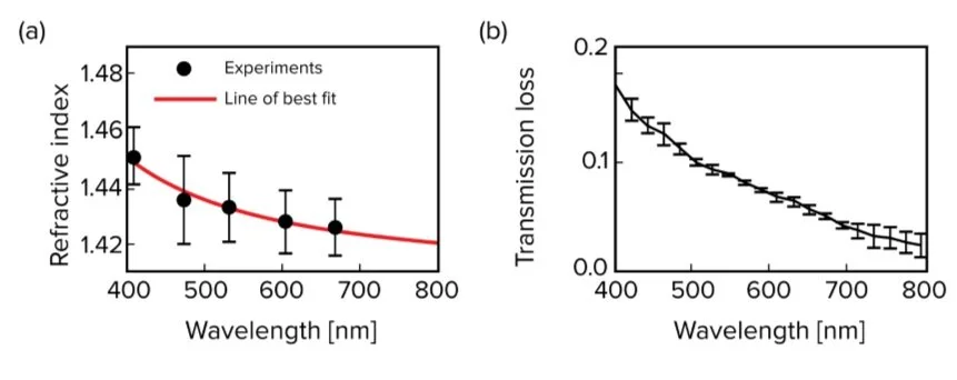
Figure 1 Optical properties of the synthesized hydrogel.
The researchers concluded that this method of production has several advantages, including cost-effectiveness, short fabrication periods, and customizability. Further, its behavior was comparable to that of conventional mass-produced hydrogen contact lenses.
Question 1: A light ray of 400 nm strikes the contact lens at an incoming angle of 30 degrees to the perpendicular. What is the angle of refraction of this light ray?
A) 90 degrees
B) 40 degrees
C) 20 degrees
D) 5 degrees
Question 2: The researchers find that at certain angles, some light passing through the hydrogel lens never crosses the boundary into the eye but instead reflects off of the boundary between media. Which of the following terms best describes this phenomenon?
A) Total internal reflection
B) Double refraction
C) Doppler effect
D) Lens aberration
Question 3: Which of the following statements about the convex contact lens are true?
I. The contact lens has a positive focal length
II. The contact lens produces inverted, real images
III. The contact lens produces a negative image distance
A) I only
B) II only
C) I and II only
D) I, II, and III
Question 4: Which of the following phenomena could be responsible for the transmission loss at higher wavelengths?
A) The Doppler effect, which results in higher aberrations at lower wavelengths
B) Reduction of power, which comes from increasing the focal length of the lens
C) Selective absorption, which filters out wavelengths that are not important for retinal imaging
D) Lens aberration, which results in the diffuse scattering of light
Question 5: What is the approximate energy of a single photon of the light that produces the lowest measured refractive index?
A) 3 * 10-19 J
B) 5 * 10-16 J
C) 2 * 10-33 J
D) 8 * 10-23 J
Answer key for passage-based problems
1. Answer choice C is correct. For this question, we use Snell’s law and any of the data points.
n1 × sinθ1 = n2 × sinθ2 where n1 = 1 is the index of refraction of air and n2 = 1.45 is the index of refraction of the hydrogel at a wavelength of 400 nm. Thus,
1 × sin(30) = 1.45 × sinθ2
1 × 0.5 = 1.45 × sinθ2
0.5/1.45 ≈ 1/3 = sinθ2
θ2 = arcsin(0.33) = 20°
2. Answer choice A is correct. Total internal reflection occurs when light crosses from a material with a high index of refraction to one with a low index of refraction at an angle that would, according to Snell’s law, generate a reflected angle of more than 90 degrees. Since this angle of reflection is not possible, the incident light is instead reflected off the boundary (choice A is correct). Double refraction occurs when a polarization-dependent index of refraction splits incident light into light beams of differing polarization (choice B is incorrect). The Doppler effect describes a change in the frequency of a wave that is the result of a relative motion between a wave source and its observer (choice C is incorrect). Lens aberration refers to the imprecision of focal lengths that is observed in real-world lenses (choice D is incorrect).
3. Answer choice C is correct. A convex lens always has a positive focal length, object distance, and image distance. Further, convex lenses produce a real and inverted image when the object is placed beyond the focal length. This is true for most objects viewed with the contact lens. Thus, statements I and II are true (choice C is correct). The contact lens should not produce a negative image distance.
4. Answer choice D is correct. Any real-world lens exhibits lens aberration, in which the focal length of the lens slightly varies. Large amounts of aberration result in a loss of focus and dispersion of light (choice D is correct). The Doppler effect should not result in an appreciable loss of transmission power (choice A is incorrect). While the reduction of power, which is inversely proportional to focal length, would result in an increase in the focal length, this phenomenon does not explain the loss of light transmission (choice B is incorrect).
5. Answer choice A is correct. The energy of one photon of light is given by E = h × f, where h is Planck’s constant and f is the frequency. Frequency is also given as f = c/λ, where λ is the wavelength of light and c is equal to the speed of light in a vacuum. Since the question asks us to determine the frequency that elicits the lowest measured refractive index, the wavelength in question is λ = 680 nm. Thus, the energy transmitted by the photon is:
E = hf = hc/λ
h = 6.6 × 10⁻³⁴ J · s
c = 3.0 × 10⁸ m/s
E = (6.6 × 10−34 × 3 × 108)/(6.8 × 10−7) = (19.8 × 10⁻²⁶)/(6.8 × 10−7)
E = 2.90 × 10⁻¹⁹ J ≈ 3 × 10⁻¹⁹ J
-----
Part 7: Standalone questions and answers
Question 1: Astronomers have found a small star moving away from the earth at a very high speed, and wish to catalog the frequency of light it emits. Which of the following phenomena are most likely to alter the observed frequency?
A) Lens aberration, which will make the light less focused
B) Redshift, which will make the light seem lower frequency
C) Blueshift, which will make the light seem higher frequency
D) Double refraction, which will separate the light into polarized rays
Question 2: A ray of light travels from a medium with an index of refraction of 1.5 into a material with an index of refraction of 2.0. The observed angle of entry is 15 degrees from the vertical. At what angle will it deflect in the new material?
A) 11 degrees
B) 45 degrees
C) 90 degrees
D) 120 degrees
Question 3: What is the smallest non-zero energy that an object can absorb from the light of wavelength 300 nm?
A) 300 * h * c
B) 300 / c
C) c * h / 300
D) c * h / (3 * 10-7)
Question 4: An object is placed 1 meter away from a lens, and its image is observed 2 meters away from the same lens. What is the strength of the lens?
A) 1/3 diopters
B) 2/3 diopter
C) 1 diopter
D) 3/2 diopters
Answers to standalone practice questions
1. Answer choice B is correct. Due to the presence of relative motion of the star moving away from Earth, the Doppler effect will change the observed apparent frequency. Redshift and blueshift describe two forms of the Doppler effect. Redshift occurs when a source travels away from the observer, making the frequency appear to be lower than the actual value (choice B is correct). Blueshift occurs when a source travels toward the observer, making the frequency appear higher than the actual value (choice C is incorrect).
2. Answer choice A is correct. To solve this question, simply use Snell’s law:
n1 × sinθ1 = n2 × sinθ2
n1 = 1.5
n2 = 2
θ1 = 15°
1.5 × sin(15°) = 2 × sinθ2
(1.5 × sin(15°))/2 = sinθ2
0.388 = sinθ2
0.194 = sinθ2
arcsin(0.194) = θ2
θ2 ≈ 11°
(choice A is correct).
3. Answer choice D is correct. The smallest possible energy that can be absorbed is the energy of one photon. The formula for photon energy is simply the frequency times Planck’s constant, h (choice B is incorrect). The frequency of the light is equal to the speed of light, c, divided by its wavelength (choice A is incorrect). The final form of the answer must include c/300, or the frequency of this light, times h. However, the wavelength of nanometers must be converted into standard units of meters (choice D is correct).
4. Answer choice D is correct. Lens strength is given by 1/f and is provided in units of diopters. The focal length can be found using the thin lens equation:
1/f = 1/o + 1/i
1/f = 1/1 + 1/2
1/f = (2 + 1)/2
1/f = 3/2
P = 1/f = 3/2
Not ready to commit to your MCAT prep at this time?
Enter your name and email for a free MCAT question delivered straight to your inbox daily.